

SCANOLOGY has just introduced NimbleTrack Gen2. With upgraded technology, SCANOLOGY's NimbleTrack Gen2 is capable of scanning large and complex areas significantly faster, while maintaining measurement-level accuracy. This is the next generation of the company's mobile optical tracking and 3D scanning systems. SCANOLOGY's NimbleTrack Gen2 is designed to deliver higher performance, especially in speed and measurement range.
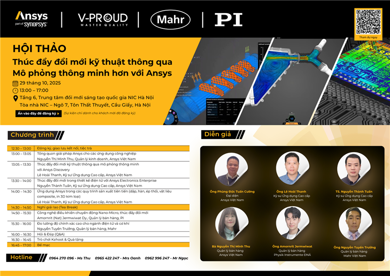
A breakthrough opportunity for R&D processes awaits the Vietnamese engineering community. The specialized workshop "Driving Engineering Innovation Through Smart Simulation" organized by ANSYS will take place on October 29, 2025, at the Innovation Hub Building, updating the latest advanced simulation solutions for the manufacturing, electronics design, and Nano-Micro industries.
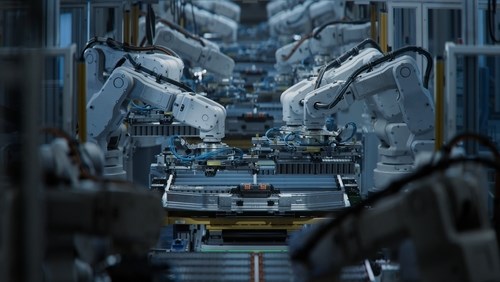
In the global race to automate manufacturing, China is emerging as a pioneer with the “dark factory” model – where robots and artificial intelligence completely replace humans. Requiring no light or rest, the new generation of factories operate continuously 24/7 with superior precision and efficiency.
Since not every burr is problematic, it should be possible to restrict the automatic search to specific workpiece areas and parameters of the burrs to be detected in an application-specific manner.
In addition to determining geometric properties such as dimensions as well as shape and position tolerances, burr inspection is one of the most important tasks in the quality assurance of plastic workpieces. Computed tomography, in combination with intelligent software, enables fast inspection with high reliability.
Burrs can form during the manufacture of workpieces in injection molding, die casting, or stretch blow molding, and also during machining. In plastic injection molding, a burr occurs when two mold forms do not close completely or only with an offset. One cause is that the molds can only be manufactured to fit accurately within certain tolerances. In addition, there is wear as well as injection parameters that are not optimally set, such as injection pressure. Burrs can cause visual blemishes or even functional limitations of the workpieces.
The automatic detection of burrs is a major challenge for metrology. For production monitoring, many workpieces have to be evaluated in a short time. Since not every burr is problematic, it should be possible to restrict the automatic search to specific workpiece areas and parameters of the burrs to be detected in an application-specific manner.
Burr Detection Integrated in the Measuring Sequence
Burrs and chips on plastic or metal workpieces can be automatically measured with the WinWerth measuring software in combination with other geometric properties such as distances or form and position deviations in a single measuring sequence. The burr detection can be taught in on one workpiece and subsequently applied to all workpieces of the same type measured with computed tomography (CT).
On the workpiece volume created during the measurement, the areas to be inspected are first marked by applying 2D or 3D windows. These windows are available as rectangle or any polygon, cylinder, and tube windows. Height, width, as well as depth or diameter can be changed graphically and interactively and the windows can be rotated in all directions. The windows can be used to define different parameters for different workpiece areas. It is possible to set several windows and then define parameters that apply to all these windows. Later, new windows with other parameters can be set.
The automatic burr detection can also be taught offline. The operator can create the measuring program in the office while the coordinate measuring machine is used for measurements on the shop floor. In this way, it is possible to complete the measurement sequence before the first workpiece is produced and to measure it immediately. For this purpose, the windows can be created based on the CAD model. For example, clicking on a line in the CAD model generates a hose window, the diameter of which can also be adjusted directly in the 3D graphics.
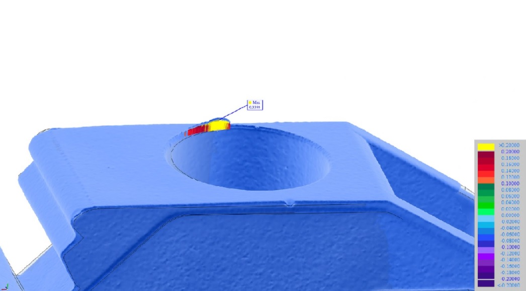
After setting the desired windows, the operator enters the minimum and maximum burr thickness of interest and the allowable tolerance for the burr length. Burrs thinner than the minimum defined burr thickness are not considered. The maximum burr thickness is used to distinguish between thin workpiece areas and should be selected significantly smaller than this, but larger than the burrs to be expected. The result is a color-coded deviation representation of the burr and the maximum burr length.
The color coding can be selected individually; in the standard display, green and blue areas indicate deviations within the tolerances, above and below the set point, respectively. Similarly, red and violet areas indicate deviations outside the tolerances. Two additional color bars mark deviations beyond the red and violet areas and thus clearly outside the tolerances.
Status Display for Multi-Object Measurements
CT measurements during production are ideal for plastic workpieces that are manufactured in large quantities. Such workpieces are also frequently found in the packaging industry. Examples are yogurt pots, bottle lids, but also dowels or plastic housings for medical technology have to be inspected. Several small workpieces, such as plastic gears, can be measured together as a group using suitable fixtures and then automatically separated by the measuring software after the measurement. This achieves a reduction of the measurement time to a few seconds per workpiece.
For the group of workpieces, an overview display appears in the 3D graphic, with CAD model of the fixture if desired, allowing quick and easy assignment of out-of-tolerance workpieces to their position in the fixture. Workpiece elements show the workpiece status, “good,” “bad,” or “above a limit,” which is determined from all specific geometric properties. Visualization takes the form of a colored sphere, in green or red for example, depending on the defined tolerance values.
Right-clicking on the workpiece element of interest opens a selection list with the result displays for the respective workpiece. Another viewer can be opened with the measurement point cloud and a graphical representation of the evaluated features. Interactive rotation makes it easier to identify problem areas than with a simple 2D image in the measurement report. The color-coded deviation display of the burrs can also be viewed via the selection list. Access to the measuring log and, if necessary, the result of a 3D nominal/actual comparison is also possible.
Quick Visual Assessment
Analysis markers allow a quick visual assessment by automatically set flags with color-coded and alphanumeric information. This feature allows the burr length to be displayed at defined intervals along the entire burr, such as every 0.5 mm. Alternatively, the desired number of flags can be entered so that the largest deviations are indicated, taking into account a minimum distance. It is also possible to display only the largest deviations to the inside and outside or only deviations outside the tolerances.
Read Quality Mastery magazine to get more information about quality management: https://qualitymastery.v-proud.vn/
If you are looking for quality management solutions, visit the following websites: v-proud.vn/product and doluongcongnghiep.vn.
Source: werthinc
(84) 896 555 247