

SCANOLOGY has just introduced NimbleTrack Gen2. With upgraded technology, SCANOLOGY's NimbleTrack Gen2 is capable of scanning large and complex areas significantly faster, while maintaining measurement-level accuracy. This is the next generation of the company's mobile optical tracking and 3D scanning systems. SCANOLOGY's NimbleTrack Gen2 is designed to deliver higher performance, especially in speed and measurement range.

A breakthrough opportunity for R&D processes awaits the Vietnamese engineering community. The specialized workshop "Driving Engineering Innovation Through Smart Simulation" organized by ANSYS will take place on October 29, 2025, at the Innovation Hub Building, updating the latest advanced simulation solutions for the manufacturing, electronics design, and Nano-Micro industries.

In the global race to automate manufacturing, China is emerging as a pioneer with the “dark factory” model – where robots and artificial intelligence completely replace humans. Requiring no light or rest, the new generation of factories operate continuously 24/7 with superior precision and efficiency.
Manufacturers of differential housings use CNC machining and turning centres, involving several operations to create a housing ready for assembly with the gear set.
Overview
Typically, a combination of various forms of gauging are used alongside the machine to monitor differential housing quality and allow engineers to correct the process. However, producers are now looking to reduce regular costly maintenance and high capital investment, as well as to improve production cycle times.
This case brief examines a typical differential housing manufacturing process with actual benefits that Renishaw technology has delivered to manufacturers who produce high quality parts, on high yield processes and are aiming for zero scrap.
Example differential housing manufacturing process* - without the Equator™ gauge
.png)
Challenges
1. Inspect different part variants on one device
Current methods of inspection involve gauges which have a high purchase cost and can only be used for one part. Many similar gauges have to be purchased to inspect all part variants. New gauges often have to be purchased for new parts as it is difficult and costly to rework and re-use existing gauges.
2. Improve process yield and quality
Drift on the machine tools is currently leading to scrap parts being produced. The aim is to produce zero scrap by improving process control.
3. Inspect critical features within machining cycle time
Inspection of critical features ensures balance and alignment of sphere centres to bores. Having multiple inspection stages can be slow, making it difficult to keep pace with production cycle times.
Inspection requirements for a differential housing
.png)
|
# |
Inspection |
Tolerance |
Why is this feature critical to part function? |
Active tool offsetting action |
|
1 |
Internal sphere diameter |
±20 µm (±0.0008”) |
Features are aligned to this central sphere. This is a critical feature for positioning the gear set. |
|
|
2 |
Alignment of pinion gear bore axis to mounting face |
± 20 µm (± 0.0008”) |
Ensures that gears engage correctly. Incorrect alignment results in high rates of wear. |
|
|
3 |
ID of gear bore axis |
+10/-6 μm (+0.0004/ -0.0002”) |
Poor fit will result in difficulty assembling differential with gear sets and outer casing. |
|
|
4 |
Distance of internal face (right) to sphere centre |
±20 μm (±0.0008”) |
Incorrect alignment when the gear is mounted on shaft will result in high rates of wear. |
|
|
5 |
Distance of internal face (left) to sphere centre |
±20 μm (±0.0008”) |
Incorrect alignment when the gear is mounted on shaft will result in high rates of wear. |
|
|
6 |
Concentricity of pinion gear bore axis to sphere axis |
45 µm (0.0018”) |
Ensures that gears engage correctly. |
|
|
7 |
Perpendicularity of pinion gear bore axis to axle axis |
60 µm (0.0024”) |
Ensures that gears engage correctly. |
|
|
8 |
Concentricity of sphere in relation to the C, D line |
45 µm (0.0018”) |
Ensures that both pinion and axle gears align. Misalignment would result in high wear and early failure of both gearsets. |
|
|
9 |
Concentricity of datum C axle bore to axle axis |
20 µm (0.0008”) |
Ensures central alignment of the axle. Incorrect alignment results in high rates of wear. |
|
|
10 |
Circularity of datum C axle bore |
20 µm (0.0008”) |
Ensures a good fit with axle, preventing poor fit and potential uneven wear. |
|
.png) Automatic update of machine offsets through inspection of indicated features.
Automatic update of machine offsets through inspection of indicated features.
Please note: In addition to the feedback of geometric features, the monitoring of form can be indicative of the health of the tools.
Process considerations
Renishaw engineers considered key elements within the differential housing manufacturing process using Renishaw’s Productive Process Pyramid™. This framework is used to identify and control the variations that can occur at key stages of the machining process.
For this process, methods to control variation include machine maintenance and calibration, tool breakage detection and shop-floor gauging for inspection and automatic feedback.
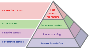
Productive Process Pyramid
Manufacturing process - opportunities for improvement
.png)
Typical results
A key action for differential housing manufacturers has been to install the Equator gauging system, consolidating
inspection activities taken at three stages onto one device, reducing capital and ongoing costs. This has also streamlined inspection, with critical features now inspected within the machining cycle time. Automatic tool offset feedback has enabled the features to be produced closer to nominal, improving yields and quality.
|
# |
Inspection Total time: 2 mins 45 secs |
Tolerance |
Gauge R&R % of tol* |
Gauge R&R range* |
|
1 |
Internal sphere diameter |
±20 µm (±0.0008”) |
1.5% |
0.5 µm (20 µin) |
|
2 |
Alignment of pinion gear bore axis to mounting face |
± 20 µm (± 0.0008”) |
3.7% |
1.1 µm (43 µin) |
|
3 |
ID of gear bore axis |
+10/-6 μm (+0.0004/ -0.0002”) |
6.0% |
0.7 µm (28 µin) |
|
4 |
Distance of internal face (right) to sphere centre |
±20 μm (±0.0008”) |
4.5% |
1.4 µm (55 µin) |
|
5 |
Distance of internal face (left) to sphere centre |
±20 μm (±0.0008”) |
5.0% |
1.5 µm (59 µin) |
|
6 |
Concentricity of pinion gear bore axis to sphere axis |
45 µm (0.0018”) |
3.2% |
2.7 µm (106 µin) |
|
7 |
Perpendicularity of pinion gear bore axis to axle axis |
60 µm (0.0024”) |
3.3% |
2.1 µm (83 µin) |
|
8 |
Concentricity of sphere in relation to the C, D line |
45 µm (0.0018”) |
1.3% |
0.8 µm (31 µin) |
|
9 |
Concentricity of datum C axle bore to axle axis |
20 µm (0.0008”) |
6.9% |
1.4 µm (55 µin) |
|
10 |
Circularity of datum C axle bore |
20 µm (0.0008”) |
3.2% |
1.0 µm (39 µin) |
1. All variants inspected in one operation
Equator™ gauging systems are inspecting all required dimensions including the position and geometric form features without the need for other inspection devices. The Equator gauge inspects 10 critical features and sends 6 offset updates to the machine tool controllers.
2. Improved process yield and quality
Equator gauging systems provide fully automated offset compensation using IPC software. Equator gauging data on critical features is constantly monitored. When any tool offset updates are required they are sent to the CNC control, adjusting the machining of subsequent parts to bring the features back towards the nominal value. Constant control of process drift has resulted in improvements to CpK above 1.67
3. Critical features inspected within cycle time
High speed scanning, plus the ability to gauge every feature means cycle time is being met and 100% of parts are inspected. The Equator gauging system has been programmed to inspect multiple part designs and variants. Capital outlay and ongoing costs have been reduced as multiple separate gauges are no longer required. Part selection takes seconds and has reduced the change over time compared to previous manual gauges. The ability of the Equator gauging system to inspect geometric features has freed up CMMs for QA tasks.
(84) 896 555 247